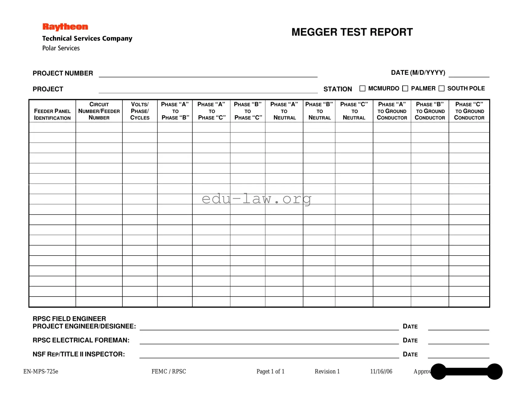
The Megger Test Report is an essential document used in electrical testing to ensure the safety and reliability of electrical systems. This form captures critical information about the project, including the project number, station, and date, which helps in tracking and organizing test results. It identifies specific feeder panels and circuit numbers, providing clarity on the components being tested. The report details voltage readings across various phases, including phase-to-phase and phase-to-neutral measurements. Additionally, it includes ground conductor readings, which are vital for assessing the integrity of the electrical system. The form is signed off by key personnel, including the RPSC field engineer and the project engineer or designee, ensuring accountability and thoroughness in the testing process. By documenting these aspects, the Megger Test Report plays a crucial role in maintaining electrical safety standards and facilitating effective communication among project stakeholders.
MEGGER TEST REPORT
PROJECT NUMBER
PROJECT |
|
STATION |
DATE (M/D/YYYY)
MCMURDO PALMER SOUTH POLE
FEEDER PANEL IDENTIFICATION
CIRCUIT
NUMBER/FEEDER
NUMBER
VOLTS/
PHASE/
CYCLES
PHASE “A”
TO
PHASE “B”
PHASE “A”
TO
PHASE “C”
PHASE “B”
TO
PHASE “C”
PHASE “A”
TO
NEUTRAL
PHASE “B”
TO
NEUTRAL
PHASE “C”
TO
NEUTRAL
PHASE “A”
TO GROUND CONDUCTOR
PHASE “B”
TO GROUND CONDUCTOR
PHASE “C”
TO GROUND CONDUCTOR
RPSC FIELD ENGINEER |
|
|
|
|
|
|
PROJECT ENGINEER/DESIGNEE: |
|
|
|
|
DATE |
|
RPSC ELECTRICAL FOREMAN: |
|
|
|
|
DATE |
|
NSF REP/TITLE II INSPECTOR: |
|
|
|
|
DATE |
|
FEMC / RPSC |
Paget 1 of 1 |
Revision 1 |
11/16//06 |
Approved by Wayne L. Cornell |
||
| Fact Name | Description |
|---|---|
| Project Number | This identifies the specific project associated with the Megger Test report. |
| Project Station | The report specifies the location of the project, such as McMurdo, Palmer, or South Pole. |
| Date | The date of the test is recorded in the format M/D/YYYY. |
| Feeder Panel Identification | This section identifies the specific feeder panel being tested. |
| Circuit Number/Feeder Number | The report includes the circuit or feeder number for reference. |
| Voltage and Phase Information | Details about voltage, phase, and cycles are included for each phase comparison. |
| Phase Comparisons | Measurements between phases A, B, and C, as well as to neutral and ground, are documented. |
| Field Engineer | The report requires the name of the RPSC field engineer responsible for the test. |
| Project Engineer/Designee | The project engineer or their designee must sign and date the report. |
| NSF Representative/Inspector | Signature and title of the NSF representative or II inspector are required for validation. |
Filling out the Megger Test form is essential for documenting electrical testing results. This form captures critical information regarding various electrical parameters, ensuring compliance and safety standards are met. Follow the steps below to accurately complete the form.
What is the purpose of the Megger Test form?
The Megger Test form is used to document the results of insulation resistance testing on electrical systems. This testing helps ensure that electrical components are functioning correctly and safely. By measuring the insulation resistance between conductors and ground, the form provides essential data for assessing the integrity of electrical installations.
What information is required on the Megger Test form?
The Megger Test form requires several key pieces of information. This includes the project number, project station, date of the test, feeder panel identification, and circuit number. Additionally, it records voltage levels and insulation resistance measurements between various phases and neutral connections. These details are crucial for accurately assessing the electrical system's condition.
Who is responsible for filling out the Megger Test form?
The form should be filled out by qualified personnel, typically an RPSC field engineer or a project engineer. Their expertise ensures that the data collected is accurate and reliable. It is also common for an electrical foreman to review the results before finalizing the documentation.
How are the test results interpreted on the Megger Test form?
Test results are interpreted based on the insulation resistance values recorded for each phase and neutral connection. Higher resistance values indicate better insulation quality, while lower values may signal potential issues. Industry standards often dictate acceptable resistance levels, which can help determine whether further action is necessary.
What should be done if the Megger Test results are unsatisfactory?
If the Megger Test results indicate low insulation resistance, further investigation is required. This may involve inspecting the electrical components for damage, moisture, or other factors that could affect insulation quality. Remedial actions might include repairing or replacing faulty components to ensure safety and compliance with electrical standards.
How long should the Megger Test form be retained?
It is advisable to retain the Megger Test form for a minimum of several years, depending on regulatory requirements and company policy. Keeping these records helps track the maintenance and testing history of electrical systems, which can be valuable for future inspections or audits.
When filling out the Megger Test form, it’s easy to make mistakes that could lead to inaccurate results or delays in processing. Here’s a list of common errors to avoid:
By paying attention to these details, you can help ensure that the Megger Test form is filled out accurately and completely, facilitating a smoother testing process.
The Megger Test form is an essential document used in electrical testing to ensure the integrity of insulation in electrical systems. Along with this form, several other documents play a crucial role in maintaining safety and compliance. Here are four commonly used forms and documents that often accompany the Megger Test report.
These documents, when used in conjunction with the Megger Test form, contribute to a thorough and effective testing process. They help ensure that electrical systems are not only functional but also safe for use.
The Megger Test Report shares similarities with a Circuit Inspection Report. Both documents serve to assess the integrity of electrical systems. A Circuit Inspection Report typically includes details about voltage readings, circuit identification, and any anomalies found during the inspection. Like the Megger Test Report, it documents the findings in a structured format, making it easy for engineers and technicians to understand the condition of the circuit.
Another document akin to the Megger Test Report is the Electrical Safety Inspection Report. This report focuses on safety compliance within electrical systems. It outlines various tests conducted, including insulation resistance tests similar to those performed in a Megger Test. Both documents emphasize the importance of safety and provide a clear record of the testing process and results.
The Transformer Test Report is also similar to the Megger Test Report. This document details the testing of transformers, including insulation resistance and winding resistance tests. Just like the Megger Test, it provides specific measurements and observations that help determine the operational status of the equipment. Both reports are crucial for ensuring reliability in electrical systems.
An Equipment Maintenance Log can be compared to the Megger Test Report in that both documents track the performance and condition of electrical equipment over time. The Maintenance Log records routine inspections and repairs, while the Megger Test Report focuses on specific tests. Together, they provide a comprehensive view of equipment health and maintenance needs.
The Commissioning Report is another document that aligns with the Megger Test Report. Commissioning Reports are created to verify that electrical systems are installed correctly and functioning as intended. They include test results, including insulation resistance, much like the Megger Test. Both documents play a vital role in ensuring that systems are safe and effective before they go into operation.
The Load Test Report shares similarities with the Megger Test Report as well. This document evaluates how well electrical systems perform under load conditions. It often includes measurements of voltage and current, akin to the readings found in the Megger Test. Both reports help identify potential issues before they escalate into larger problems.
The Inspection and Test Plan (ITP) is comparable to the Megger Test Report in that it outlines the testing and inspection processes for electrical systems. The ITP specifies what tests will be conducted, including insulation tests, similar to those performed in a Megger Test. Both documents ensure that all necessary evaluations are completed to maintain system integrity.
The Condition Assessment Report is another document that parallels the Megger Test Report. This report evaluates the current state of electrical equipment, often using tests like insulation resistance. Both reports aim to identify any weaknesses or potential failures in the system, helping to inform maintenance and repair strategies.
The Final Inspection Report can be likened to the Megger Test Report as both documents provide a summary of testing and inspection results. The Final Inspection Report typically includes a checklist of tests performed, including insulation resistance tests. This ensures that all aspects of the electrical system have been evaluated before it is deemed operational.
Lastly, the Compliance Report is similar to the Megger Test Report in that it verifies adherence to safety and operational standards. This report may include various test results, including those from insulation resistance tests. Both documents are essential for demonstrating that electrical systems meet regulatory requirements and are safe for use.
When filling out the Megger Test form, attention to detail is crucial. Here are six important guidelines to consider:
Understanding the Megger Test form is crucial for accurately assessing electrical insulation. However, several misconceptions can lead to confusion. Here are ten common misconceptions:
By addressing these misconceptions, users can better understand the Megger Test and its applications, leading to improved electrical safety and reliability.
When filling out and using the Megger Test form, it is essential to follow specific guidelines to ensure accuracy and reliability. Here are some key takeaways:
By adhering to these guidelines, the Megger Test form will serve as a reliable document for electrical testing and analysis.