The Manual J form is an essential tool for calculating heating and cooling loads in residential buildings. This form is specifically designed to address the unique climate conditions found in Utah, particularly its dry climate. It requires detailed information about the project location, design conditions, and specific equipment to be used. The form includes sections for assessing heat loss and gain, which must be calculated on a room-by-room basis. This breakdown is crucial for accurate duct sizing, which is addressed in the Manual D calculations. Users must provide data on various factors, including construction quality, infiltration methods, and the characteristics of heating and cooling equipment. Additionally, the form emphasizes the importance of justifying any deviations from standard design conditions, ensuring that all calculations align with the specific requirements of the project. By following the guidelines set forth in the Manual J form, contractors can ensure that HVAC systems are properly sized and efficient, ultimately leading to improved comfort and energy savings for homeowners.

Building Services & Civil Enforcement slcpermits.com
451 South State Street, Room 215 |
PO Box 145490 |
Salt Lake City, Utah 84111 |
Salt Lake City, Utah |
Office only |
Updated 12/2012 |
BLD # Received by
Date Valuation
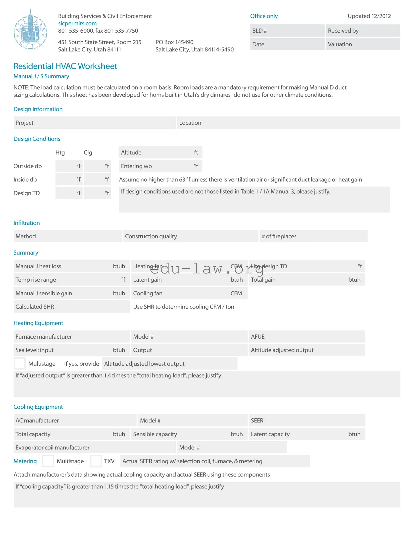
Residential HVAC Worksheet
Manual J / S Summary
NOTE: The load calculation must be calculated on a room basis. Room loads are a mandatory requirement for making Manual D duct sizing calculations. This sheet has been developed for homs built in Utah’s dry dimares- do not use for other climate conditions.
Design Information |
|
|
|
|
|
|
|
|
|
|
|
|
|
|
|
|
|
|
|
|
|
|
|
|
|
|||||
|
|
|
|
|
|
|
|
|
|
|
|
|
|
|
|
|
|
|
|
|
|
|
|
|
|
|
|
|
|
|
|
Project |
|
|
|
|
|
|
|
|
|
|
|
|
|
|
Location |
|
|
|
|
|
|
|
|
|
|
|
|||
|
|
|
|
|
|
|
|
|
|
|
|
|
|
|
|
|
|
|
|
|
|
|
|
|
|
|
|
|
|
|
Design Conditions |
|
|
|
|
|
|
|
|
|
|
|
|
|
|
|
|
|
|
|
|
|
|
|
|
|
|||||
|
|
|
|
|
|
|
|
|
|
|
|
|
|
|
|
|
|
|
|
|
|
|
|
|
|
|
|
|
||
|
|
Htg |
Clg |
|
|
Altitude |
|
|
ft |
|
|
|
|
|
|
|
|
|
|
|
|
|
||||||||
|
|
|
|
|
|
|
|
|
|
|
|
|
|
|
|
|
|
|
|
|
|
|
|
|
|
|
|
|
|
|
|
|
|
|
|
|
|
|
|
|
|
|
|
|
|
|
|
|
|
|
|
|
|
|
|
|
|
|
|||
Outside db |
|
|
°f |
|
|
°f |
|
Entering wb |
|
|
°f |
|
|
|
|
|
|
|
|
|
|
|
|
|
||||||
|
|
|
|
|
|
|
|
|
|
|
|
|
|
|
|
|
|
|
|
|
|
|
|
|
|
|
|
|
||
|
|
|
|
|
|
|
|
|
|
|
|
|
|
|
|
|
||||||||||||||
Inside db |
|
|
°f |
|
|
°f |
|
Assume no higher than 63 °f unless there is ventilation air or significant duct leakage or heat gain |
||||||||||||||||||||||
|
|
|
|
|
|
|
|
|
|
|
|
|
|
|
|
|
|
|
|
|
|
|
|
|
|
|
|
|||
|
|
|
|
|
|
|
|
|
|
|
|
|
|
|
|
|
|
|
|
|
|
|
|
|
|
|
|
|
|
|
Design TD |
|
|
°f |
|
|
°f |
|
If design conditions used are not those listed in Table 1 / 1A Manual 3, please justify. |
|
|
|
|
||||||||||||||||||
|
|
|
|
|
|
|
|
|
|
|
|
|
|
|
|
|
|
|
|
|
|
|
|
|
|
|
||||
|
|
|
|
|
|
|
|
|
|
|
|
|
|
|
|
|
|
|
|
|
|
|
|
|
|
|
|
|
|
|
Infiltration |
|
|
|
|
|
|
|
|
|
|
|
|
|
|
|
|
|
|
|
|
|
|
|
|
|
|
|
|
|
|
|
|
|
|
|
|
|
|
|
|
|
|
|
|
|
|
|
|
|
|
|
|
|
|
|
|
|
|
|
||
|
|
|
|
|
|
|
|
|
|
|
|
|
|
|
|
|
|
|
|
|
|
|
|
|
|
|
|
|
|
|
|
Method |
|
|
|
|
|
|
|
|
Construction quality |
|
|
|
|
|
|
|
|
# of fireplaces |
|
|
|
|
|
||||||
|
|
|
|
|
|
|
|
|
|
|
|
|
|
|
|
|
|
|
|
|
|
|
|
|
|
|
|
|
|
|
Summary |
|
|
|
|
|
|
|
|
|
|
|
|
|
|
|
|
|
|
|
|
|
|
|
|
|
|
|
|
|
|
|
|
|
|
|
|
|
|
|
|
|
|
|
|
|
|
|
|
|
|
|
|
|
|
|
|
|
||||
|
Manual J heat loss |
|
|
|
|
btuh |
|
Heating fan |
|
|
|
|
CFM |
|
Htg design TD |
|
°f |
|
|
|
||||||||||
|
|
|
|
|
|
|
|
|
|
|
|
|
|
|
|
|
|
|
|
|
|
|
|
|
|
|
|
|||
|
|
|
|
|
|
|
|
|
|
|
|
|
|
|
|
|
|
|
|
|
|
|
|
|
|
|
|
|||
|
Temp rise range |
|
|
|
|
to |
|
|
°f |
|
Latent gain |
|
|
|
|
btuh |
|
Total gain |
|
|
btuh |
|
|
|
||||||
|
|
|
|
|
|
|
|
|
|
|
|
|
|
|
|
|
|
|
|
|
|
|
|
|
|
|
|
|
||
|
|
|
|
|
|
|
|
|
|
|
|
|
|
|
|
|
|
|
|
|
|
|
|
|
|
|
|
|
||
|
Manual J sensible gain |
|
|
|
btuh |
|
Cooling fan |
|
|
|
|
CFM |
|
|
|
|
|
|
|
|
|
|
||||||||
|
|
|
|
|
|
|
|
|
|
|
|
|
|
|
|
|
|
|
|
|
|
|
|
|
|
|
|
|
|
|
|
|
|
|
|
|
|
|
|
|
|
|
Use SHR to determine cooling CFM / ton |
|
|
|
|
|
|
|
|
|
|
||||||||
|
Calculated SHR |
|
|
|
|
|
|
|
|
|
|
|
|
|
|
|
|
|
|
|
|
|||||||||
|
|
|
|
|
|
|
|
|
|
|
|
|
|
|
|
|
|
|
|
|
|
|
|
|
|
|
|
|
|
|
Heating Equipment |
|
|
|
|
|
|
|
|
|
|
|
|
|
|
|
|
|
|
|
|
|
|
|
|
|
|||||
|
|
|
|
|
|
|
|
|
|
|
|
|
|
|
|
|
|
|
|
|
|
|
|
|
|
|
|
|||
|
Furnace manufacturer |
|
|
|
|
|
|
|
Model # |
|
|
|
|
|
|
|
AFUE |
|
|
|
|
|
|
|||||||
|
|
|
|
|
|
|
|
|
|
|
|
|
|
|
|
|
|
|
|
|
|
|
|
|
|
|
|
|||
|
|
|
|
|
|
|
|
|
|
|
|
|
|
|
|
|
|
|
|
|
|
|
|
|
|
|
|
|||
|
Sea level: input |
|
|
|
|
|
|
btuh |
|
Output |
|
|
|
|
|
|
|
Altitude adjusted output |
|
|
|
|
||||||||
|
|
|
|
|
|
|
|
|
|
|
|
|
|
|
|
|
|
|
|
|
|
|
|
|
|
|
|
|||
|
Multistage |
|
If yes, provide |
|
|
|
|
|
|
|
|
|
|
|
|
|
|
|
|
|
|
|
||||||||
|
|
Altitude adjusted lowest output |
|
|
|
|
|
|
|
|
|
|
|
|
|
|||||||||||||||
|
|
|
|
|
|
|
|
|
|
|
|
|
|
|
|
|
|
|
|
|
|
|
|
|
|
|||||
|
|
|
|
|
|
|
|
|
|
|
|
|
|
|
|
|
|
|
|
|
|
|
|
|
||||||
|
If “adjusted output” is greater than 1.4 times the “total heating load”, please justify |
|
|
|
|
|
|
|
|
|
|
|||||||||||||||||||
|
|
|
|
|
|
|
|
|
|
|
|
|
|
|
|
|
|
|
|
|
|
|
|
|
|
|
|
|
|
|
Cooling Equipment |
|
|
|
|
|
|
|
|
|
|
|
|
|
|
|
|
|
|
|
|
|
|
|
|
|
|||||
|
|
|
|
|
|
|
|
|
|
|
|
|
|
|
|
|
|
|
|
|
|
|
|
|
|
|
|
|||
|
AC manufacturer |
|
|
|
|
|
|
|
|
|
Model # |
|
|
|
|
|
|
|
SEER |
|
|
|
|
|
|
|||||
|
|
|
|
|
|
|
|
|
|
|
|
|
|
|
|
|
|
|
|
|
|
|
|
|
|
|
||||
|
|
|
|
|
|
|
|
|
|
|
|
|
|
|
|
|
|
|
|
|
|
|
|
|
||||||
|
Total capacity |
|
|
|
|
|
|
btuh |
|
Sensible capacity |
|
|
|
btuh |
|
Latent capacity |
|
btuh |
|
|
|
|||||||||
|
|
|
|
|
|
|
|
|
|
|
|
|
|
|
|
|
|
|
|
|
|
|
|
|
|
|
|
|||
|
|
|
|
|
|
|
|
|
|
|
|
|
|
|
|
|
|
|
|
|
|
|
|
|
|
|
|
|||
|
Evaporator coil manufacturer |
|
|
|
|
|
|
|
|
|
Model # |
|
|
|
|
|
|
|
|
|
|
|
||||||||
|
|
|
|
|
|
|
|
|
|
|
|
|
|
|
|
|
|
|
||||||||||||
|
|
Multistage |
|
TXV |
|
|
|
|
|
|
|
|
|
|
|
|
|
|
|
|
|
|
|
|
|
|
||||
Metering |
|
Actual SEER rating w/ selection coil, furnace, & metering |
|
|
|
|
|
|
||||||||||||||||||||||
|
|
|
|
|
|
|
|
|
|
|
|
|
|
|
|
|
|
|
|
|
|
|
|
|
|
|
|
|
|
|
Attach manufacturer’s data showing actual cooling capacity and actual SEER using these components
If “cooling capacity” is greater than 1.15 times the “total heating load”, please justify
Manual J / S Summary
Instructions
The load information asked for on the summary must be taken from the actual load calculation completed on the project.
Project
Identify project name, lot number- information that matches the plan submitted.
Location
The city or town must be reasonably close to actual location. Software used may not have the specific location in the database.
Outside Dry Bulb, Inside Dry Bulb
Temperature data should be from Table 1 or Table 1A of ACCA Manual J. It is understood that there may be situations where a slight adjustment to this values is necessary. For example; there may be areas in the Salt Lake Valley where the low temperature is historically lower than the airport temperature. If values are adjusted- please justify the adjustment. Provide both heating (htg) and cooling (clg) design temperatures. If inside
or outside design conditions listed are not the same values listed in Manual J, explain why the different values were used.
Entering WB
The entering
63 °f (75 °f dry bulb) relative humidity). A higher wb temperature will result from duct leakage,
air temperature. Use this wb temperature when selecting cooling condenser from manufacturer’s comprehensive data.
Design TD
TD: the temperature difference between inside and outside design temperatures.
Infiltration
Infiltration calculations are based on the Construction Quality. Version 7 of Manual ] uses Best, Average or Poor to evaluate Infiltration. Version 8AE uses Tight,
not be counted. Methods include: Simplified
/Default Method- taken from Table 5A; Component Leakage Area Method- calculating infiltration based on individual leakage points taken from Table 5C of Manual J8; or Blower Door Method, where the actual leakage is based on a blower door test on the home.
Manual J Heat Loss
This is the whole house winter heat loss taken directly from the completed attached Load Calculation. Load must account for all factors such as loss building components as well as loss through infiltration, ventilation, and duct losses.
Heating Fan
Heating airflow typically may be lower than cooling cfm. Adjusted to insure the temperature rise across the heat exchanger falls within the range specified by the manufacturer. Software will often do this calculation and provide a correct heating cfm. See Manual S Section
Manufacturer’s Temperature Rise Range
Range taken from manufacturer’s performance data. Various manufacturers may certify ranges from 20 - 70 °f.
Manual J — Sensible Gain
The whole house summer heat gain taken directly from the completed attached Load Calculation. Load must account for all factors including gain through building components, solar gain, infiltration, ventilation and ducts. Also includes the sensible internal gains from appliances and people.
Manual 3 — Latent Gain
The gains due to moisture in the air. Large latent load are typically from moisture migration into the home from outside in humid climates. People, cooking, plants, bathing and laundry washing can all add to the latent load in a home.
Total Gain
The combined total of the sensible and latent gain. May be referred to as Total Cooling Load.
SHR- Sensible Heat Ratio
Use to determine Cooling cfm per ton. The ratio of sensible heat gain to total heat gain. SHR = Sensible Heat Gain ÷ Total Heat Gain. Recommended air flows: If SHR is below 0.80 select 350 cfm / ton; if SHR is between 0.80 & 0.85 select 400 cfm; if SHR is greater than 0.85, select 450 cfm
/ton. Note: This cfm is not the final cfm; additional adjustment may be required for Altitude. See next item- Cooling Fan.
Cooling Fan
Software used to perform the calculation will typically provide a minimum cfm based on the minimum required size of the equipment. This number may be adjusted to meet specific requirements of the home. Heating and Cooling CFM may or may not be the same. The cooling CFM should be around 450 CFM per ton of cooling in Utah’s dry climates. For higher altitudes, CFM must be adjust up as detailed in ACCA / ANSI Manual S. Mountain location should expect Cooling CFM at 500 CFM per ton and higher.
HEATING
Equipment
List specific equipment to be used. This information is not required on the Load Calculation documents, however it must be provided here to verify equipment sizing against calculated loads.
AFUE
The AFUE (Annual Fuel Utilization Efficiency) listed here will be compared to that listed on plans and on energy compliance documents (RES check or other). It must also match the equipment actually installed in the home.
Sea Level Input
The listed input on the furnace label and in manufacturers’ documentation. Input represents the total amount
of heat in the gas at sea level.
Output
The amount a heat available for discharge into the conditioned space. The input less any vent or stack losses, or heat that is carried out with the products of combustion. May be take from manufacturer’s performance data or calculated using input and furnace efficiency.
Altitude Adjusted Output
This number is the actual output that will be attained after the furnace has been adjusted for efficiency and
Size Justification
Example: If the Total Heating Load = 29954 btuh. A furnace with an adjusted output larger than 45,000 btuh (29954 x 1.5 = 44931) would require an explanation justifying the size.
COOLING
Equipment
List specific equipment to be used. Provide manufacturers comprehensive data for furnace, furnace blower and condenser, with capacities at design conditions highlighted.
Condenser SEER
This SEER (Seasonal Energy Efficiency Ratio) is the listed SEER for this model series, not the exact SEER with components used this system.

Total Capacity
Manufacturers base data is based on ARI Standard 210 / 240 ratings; 95 °f outdoor air temperature, 80 °f db / 67 °f wb entering evaporator. As the Design Conditions
are different than this standard, refer to manufacturers expanded ratings for capacities at actual design conditions. Total capacity is the latent and sensible capacity at design conditions
Sensible Capacity
The sensible only capacity from the manufacturer’s expanded data at design conditions.
Manual D Calculations & Summary
Project
Friction Rate Worksheet & Steps
1Manufacturer’s Blower Data
External static pressure (ESP) |
IWC |
CFM |
|
|
|
Latent Capacity
The latent only capacity from the manufacturer’s expanded data at design conditions. NOTE: One half of the excess latent capacity may be added to the sensible capacity.
Evaporator Coil Make and Model #
List the exact model number for the evaporator coil used this system. If coil is from a different manufacturer than the condenser is used, provide data from both manufacturers verifying actual performance.
Expansion / Metering
Provide the specific metering used- orifice or TXV (thermostat expansion valve). If the manufacturer has several options, list the option used.
Actual SEER Rating
Attach manufacturers’ documentation or ARI report showing actual cooling capacity, and actual SEER using the components used this system. Indoor air handler / furnace blower must be included in this documentation. Do not use ARI (ARHI) data for actual sizing.
Size Justification
If cooling capacity is 15% greater than the calculated Cooling load explain. High latent (moisture) loads can be listed here. Special requirements particular to the customer may also be noted here.
2Device Pressure Losses
Evaporator |
Supply register |
.03 |
Other device |
|
|
|
|
|
|
|
|
|
|
|
Air filter |
Return grill |
.03 |
Total device losses (DPL) |
IWC |
|
|
|
|
|
3Available Static Pressure (ASP)
ASP = ( ESP - DPL ) IWC
4Total Effective Length (TEL)
Supply side TEL |
ft |
|
Return side TEL |
ft |
|
|
|
|
|
Total effective length (TEL) = supply side TEL + return side TEL ft
5Friction Rate Design Value (FR)
FR = ( ( 100 x ASP ) / TEL ) IWX / 100’
Mechanical Sizing
Name of contractor / designer
Phone Fax
Address
Permit # Lot #
This friction rate (FR) calculated in Step 5 is the rate to be used with a duct calculator or a friction chart for the duct design on this project.
Attach at a minimum, a one line diagram showing the duct system with fittings, sizes, equivalent lengths through fitting and duct lengths.
Vent height (base of duct to roof exit) ft

Boiler or furnace input rating |
btu |
|
|
|
|
btu |
|
|
|
|
|
Connector rise |
ft |
|
|
|
|
Connector run |
ft |
|
|
|
|
Connector size |
in |
|
|
|
|
Orifice size |
in |
|
|
|
|
Water heater input rating |
btu |
|
|
|
|
btu |
|
|
|
|
|
Connector rise |
ft |
|
|
|
|
Connector run |
ft |
|
|
|
|
Connector size |
in |
|
|
|
|
Orifice size |
in |
|
|
|
|
Total heat input of all appliances |
btu |
|
|
|
|
Vent size for the system |
in |
|
|
|
|
Combustion air size |
in² |
|
|
Signature |
|
Boiler or furnace #2 input rating btu
Connector rise ft
Connector run ft
Connector size in
Orifice size in
Water heater #2 input rating btu
Connector rise ft
Connector run ft
Connector size in
Orifice size in
Attach a complete gas pipe layout & sizing detail to the plan or permit application.
If a manifold is used to connect the appliances on the horizontal, it shall be the same size as the vent.
To the best of my knowledge, I certify that the information contained within this document is true, correct, and meets the requirements of the 2009 International Mechanical Code and International Fuel Gas Code.
Date
Mechanical Sizing Worksheet |
|
b |
Example: SLC has a 17% |
||
|
|
factor. On a 100,000 Btu furnace you |
|||
Materials needed to fill out this form are the |
|
|
multiply 100,000 x .83 = 83,000 Btu’s |
||
|
c |
On the vent sizing this becomes |
|||
International fuel gas Code and the Questar |
|
||||
Recommended Good Practices Book. |
|
|
the fan min. The fan max is the |
||
VENT SIZING |
|
|
listed input rate example fan |
||
|
|
min = 83 and fan max = 100 |
|||
1 |
Vent height is measured from the |
|
d |
The Btu to ft³ conversion number for |
|
|
draft diverter or appliance vent |
|
|
SLC is 890 and the specific gravity of |
|
|
outlet to the top of the vent cap. |
|
|
the gas is .60. Divide the new input |
|
2 |
Connector rise is the height of the vent |
|
|
rating by 890, 83,000 = 93.258 ft³. 890 |
|
|
|
|
|||
|
connector from the appliance outlet |
|
e |
Take the ft³ of input and divide it by the |
|
|
to the center of the tee in the vent at |
|
|
number of burners on the appliance, |
|
|
the point of connection to the vent. |
|
|
this will give you the ft³ / burner. Then |
|
3 |
Connector run is the horizontal distance |
|
|
use the orifice tables in the Questar |
|
|
|
handbook to determine the orifice size. |
|||
|
from the appliance vent outlet to the vent. |
|
|
||
|
|
|
Example if you have 4 burners: 93.258 |
||
|
|
|
|
||
4 |
Go to the International Fuel Gas |
|
|
ft³ / 4 burners = 23.315 ft³ / 1 burner. |
|
|
Code Chapter 5. Sizing is done to |
|
|
Match as close as possible to the |
|
|
the appropriate gamma table . |
|
|
Orifice table in the handbook. In this |
|
5 |
The gamma tables are in Btu and not ft³ |
|
|
sample the orifice size would be (49) |
|
2 |
Use the International Fuel Gas Code and the |
||||
|
International Mechanical Code to complete |
||||
|
|
|
|||
1 |
See Questar handbook for a |
|
the vent sizing and the combustion air |
||
|
sizing. See Chapter 5 IFC for the rules and |
||||
|
formula and the required conversion |
|
|||
|
|
the tables to fill out this portion of the form. |
|||
|
numbers. To complete this form: |
|
|||
|
|
ICBO also has available a commentary on |
|||
|
|
|
|||
|
a Input is |
|
the mechanical code that contains a step- |
||
|
1000’ in elevation. |
|
|||
3The International Mechanical Code commentary also contains examples to size the gas pipe. You must show the pipe lengths, the Btus and the volume of each appliance and show the size of each length of pipe. All tables necessary to size gas pipe are also contained in the International Fuel Gas Code, and in the Questar handbook.
4For Salt Lake City use:
a890 Btu per ft³
bA multiplier of .83
cSpecific gravity of .60
dCombustion air is computed at 1 in² per 3,000 Btu of input of all fuel burning appliances in the room. One duct upper 12” of the room.
EQuestar gas has a training program available to all persons and contractors.
| Fact Name | Description |
|---|---|
| Purpose | The Manual J form is used to calculate heating and cooling loads for residential HVAC systems, ensuring efficiency and comfort. |
| Room-Based Calculation | Load calculations must be performed on a room-by-room basis to accurately size HVAC systems. |
| Design Conditions | Design conditions include outside and inside temperatures, which must be documented for accurate calculations. |
| Infiltration Methods | Different methods assess air infiltration, including the Simplified Method and Blower Door Method, which influence energy efficiency. |
| Heating and Cooling Loads | The form calculates both heating (Manual J heat loss) and cooling loads (sensible and latent gains) to ensure proper HVAC sizing. |
| Altitude Adjustments | In Utah, adjustments are made for altitude when calculating heating output to ensure accurate performance. |
| Manufacturer Data | Actual manufacturer data for HVAC equipment must be attached to validate the performance claims made in the calculations. |
| Compliance with Codes | The form must comply with the 2009 International Mechanical Code and International Fuel Gas Code, ensuring safety and reliability. |
| State-Specific Requirements | In Utah, the Manual J form is specifically tailored for the dry climate conditions prevalent in the region. |
| Documentation | All adjustments, calculations, and equipment details must be thoroughly documented to support the load calculations and equipment selections. |
Filling out the Manual J form is a critical step in ensuring your HVAC system is properly sized for your home. This process requires careful attention to detail and accurate data collection. Follow the steps below to complete the form effectively.
Once you have completed the form, ensure that all necessary attachments are included. This will facilitate a smoother review process and help avoid delays in your HVAC project. Accurate data is essential for the success of your heating and cooling systems.
What is the Manual J form and why is it important?
The Manual J form is a critical document used for calculating the heating and cooling loads of a residential building. It ensures that HVAC systems are properly sized to maintain comfort and efficiency. By conducting a detailed load calculation, the form helps to avoid issues such as under-sizing or over-sizing equipment, which can lead to increased energy costs and discomfort. This form is particularly tailored for homes built in Utah’s dry climate, making it essential for accurate HVAC design in that region.
How do I fill out the Manual J form?
Filling out the Manual J form involves several key steps. First, you need to gather design information, including project location and design conditions such as heating and cooling temperatures. You must calculate room loads on a room-by-room basis, as this is mandatory for duct sizing calculations. Be sure to justify any adjustments made to standard temperature values based on local conditions. Additionally, you will need to provide details on infiltration methods, heating and cooling equipment, and any other relevant data. Accurate completion of this form is vital for ensuring that your HVAC system performs optimally.
What are the consequences of not using the Manual J form?
Failing to use the Manual J form can lead to significant issues. Without proper load calculations, HVAC systems may be improperly sized, resulting in inefficient operation. This can cause higher energy bills, inconsistent indoor temperatures, and increased wear and tear on equipment. Additionally, not following this protocol may lead to compliance issues with local building codes, potentially delaying project approvals or resulting in fines. It is essential to prioritize this step to ensure a successful and compliant HVAC installation.
How often should the Manual J calculations be updated?
Manual J calculations should be updated whenever there are significant changes to the building structure, such as renovations, additions, or changes in insulation. Additionally, if new HVAC equipment is installed or if there are changes in occupancy patterns, recalculating the loads is advisable. Regular updates ensure that the HVAC system continues to operate efficiently and effectively, adapting to any changes in the home’s requirements.
Can I use the Manual J form for climates other than Utah's dry climate?
No, the Manual J form provided is specifically developed for homes built in Utah’s dry climate. Using it in other climate conditions may yield inaccurate results. Each region has unique climate characteristics that affect heating and cooling loads, so it is essential to use the appropriate calculations and forms tailored to those specific conditions. For accurate assessments in different climates, consult the relevant local guidelines or standards.
Inaccurate Temperature Inputs: One common mistake is entering incorrect outside and inside dry bulb temperatures. These values should be taken from the appropriate tables in the Manual J guidelines. Adjustments may be necessary, but they must be justified.
Neglecting Room-by-Room Calculations: The Manual J form requires load calculations on a room-by-room basis. Failing to do this can lead to inaccurate assessments of heating and cooling needs.
Ignoring Infiltration Method: Selecting an improper method for calculating infiltration can significantly affect the results. It is essential to note the construction quality and choose the correct evaluation method, whether it’s Best, Average, or Poor.
Overlooking Equipment Specifications: Providing incorrect or incomplete specifications for heating and cooling equipment can lead to discrepancies in sizing. Ensure that all equipment details, including model numbers and efficiency ratings, are accurately filled out.
Failure to Justify Adjustments: If any values differ from those in the Manual J tables, a justification must be included. Omitting this explanation can result in delays or rejections of the form.
Not Including All Factors in Load Calculations: When calculating heat loss or gain, all factors must be considered, including building components, solar gain, and internal gains from appliances and occupants. Neglecting any of these can lead to an incomplete assessment.
The Manual J form is a crucial document used in HVAC design to calculate the heating and cooling loads for a building. However, it is often accompanied by other forms and documents that help ensure a comprehensive approach to HVAC system design and installation. Here’s a list of common forms that may be used alongside the Manual J form:
Using these forms in conjunction with the Manual J form helps streamline the HVAC design and installation process. They ensure that the system is not only correctly sized but also compliant with regulations and efficient in operation. Proper documentation is key to achieving optimal performance and comfort in any building.
The Manual J form is similar to the ACCA Manual S, which focuses on the selection of HVAC equipment. Both documents require precise load calculations to ensure that the heating and cooling systems are adequately sized for the specific conditions of a home. Just as the Manual J provides detailed calculations on heat loss and gain, the Manual S uses that information to guide the selection of appropriate equipment based on efficiency ratings and performance metrics. Accurate data from Manual J is essential for making informed decisions in Manual S, ensuring optimal system performance and energy efficiency.
Another document that shares similarities with the Manual J is the Manual D, which deals with duct design. While Manual J calculates the heating and cooling loads, Manual D focuses on how to distribute those loads effectively throughout the home. It uses the load data provided by Manual J to determine the appropriate duct sizes, layout, and airflow requirements. This ensures that the HVAC system operates efficiently and maintains comfort levels in every room, making the relationship between these two documents crucial for successful HVAC design.
The Energy Star Home Certification checklist is also comparable to the Manual J form. Both documents emphasize the importance of energy efficiency in residential construction. The Energy Star checklist outlines specific criteria that homes must meet to achieve certification, including proper insulation, efficient HVAC systems, and effective air sealing. Manual J supports this goal by providing the necessary load calculations to ensure that HVAC systems are appropriately sized and energy-efficient, aligning with Energy Star's commitment to reducing energy consumption in homes.
The ASHRAE 62.2 standard is another document that parallels the Manual J form. It focuses on ventilation requirements for residential buildings. Just as Manual J calculates heating and cooling loads, ASHRAE 62.2 outlines the necessary ventilation rates to maintain indoor air quality. Both documents are essential for creating a comfortable and healthy living environment, as they address different aspects of home performance—thermal comfort and air quality—ensuring that homes are not only energy-efficient but also safe and pleasant to live in.
The RESNET HERS Index is similar to the Manual J form in that both aim to quantify the energy performance of a home. The HERS Index provides a score that reflects a home's energy efficiency, while Manual J offers detailed calculations on heating and cooling loads. The data from Manual J can influence a home's HERS score by ensuring that HVAC systems are properly sized and efficient, contributing to overall energy savings and sustainability in residential construction.
The ICC (International Code Council) compliance documents also bear similarities to the Manual J form. Both are designed to ensure that residential buildings meet specific safety and efficiency standards. While Manual J focuses on load calculations for HVAC systems, ICC documents cover a broader range of building codes, including structural integrity and energy efficiency. The load calculations in Manual J can help ensure that HVAC systems comply with these codes, ultimately contributing to the safety and livability of the home.
Lastly, the Manual N, which addresses system performance and efficiency, is akin to the Manual J form. Manual N provides guidelines for evaluating HVAC system performance based on the loads calculated in Manual J. Both documents work together to ensure that heating and cooling systems not only meet the specific needs of a home but also operate efficiently and effectively. The data from Manual J is crucial for the assessments made in Manual N, making them complementary resources in HVAC design.
When filling out the Manual J form, attention to detail is crucial. Here are some guidelines to help you navigate the process effectively.
Misconceptions about the Manual J form can lead to misunderstandings regarding its purpose and application. Below are four common misconceptions, along with clarifications for each.
This is not true. The Manual J form is also applicable for renovations and upgrades to existing HVAC systems. Any time there is a change in the heating or cooling system, a load calculation is essential to ensure proper sizing and efficiency.
While the calculations may seem complex, they are crucial for ensuring that HVAC systems operate efficiently. Accurate load calculations can prevent issues such as inadequate heating or cooling, which can lead to increased energy costs and discomfort.
This is misleading. Manual J calculations must be tailored to the specific characteristics of each building, including its size, layout, and local climate conditions. Using generic values can result in inaccurate load assessments.
In reality, all stakeholders involved in the construction or renovation project should understand the importance of the Manual J calculations. This includes architects, builders, and homeowners, as the accuracy of the load calculation affects the overall performance of the HVAC system.
Understanding the Manual J Form is essential for accurate HVAC load calculations. Here are key takeaways to guide you through the process:
By following these guidelines, you will enhance the accuracy and reliability of your HVAC load calculations, ensuring optimal performance and comfort in the home.